GMSH2OGS anomaly

Dear OGS developers and users,

I meet an anomaly with GMSH2OGS.

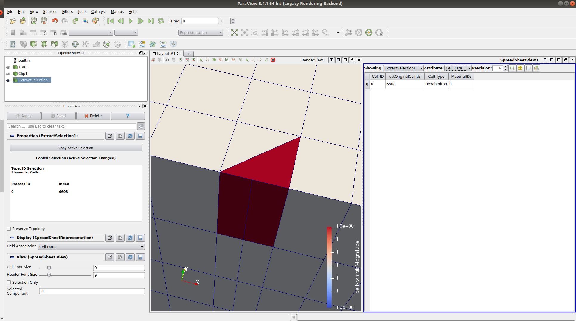
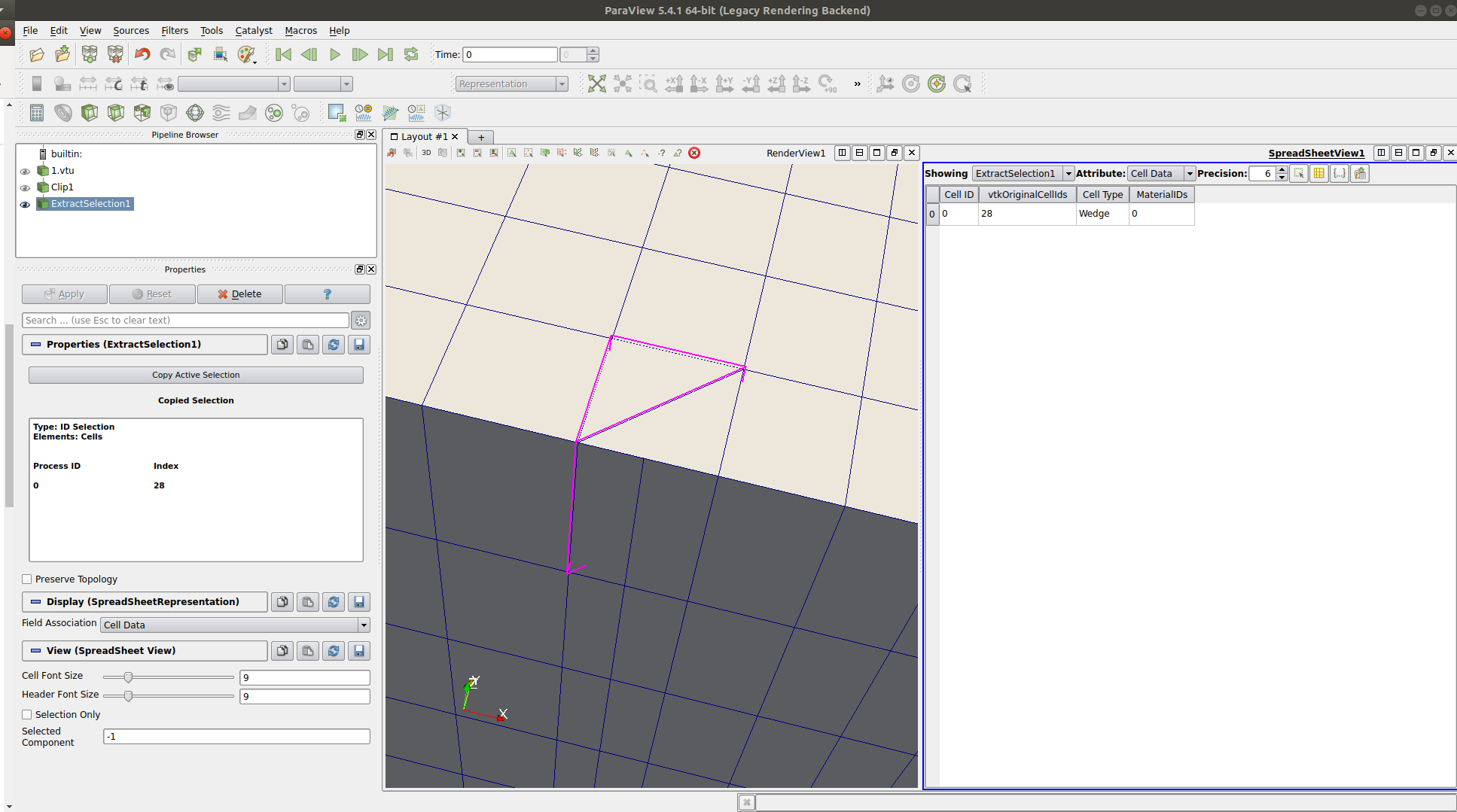
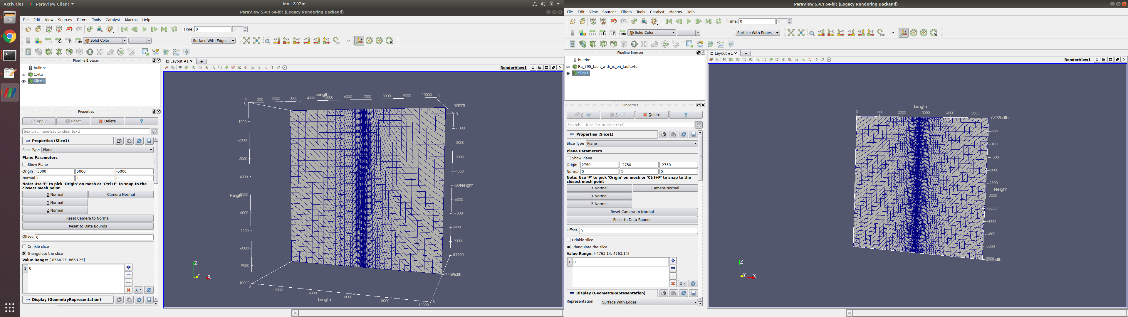
The clip (normal to the Y direction) of the model is shown in the picture (.vtu file opened with Paraview).

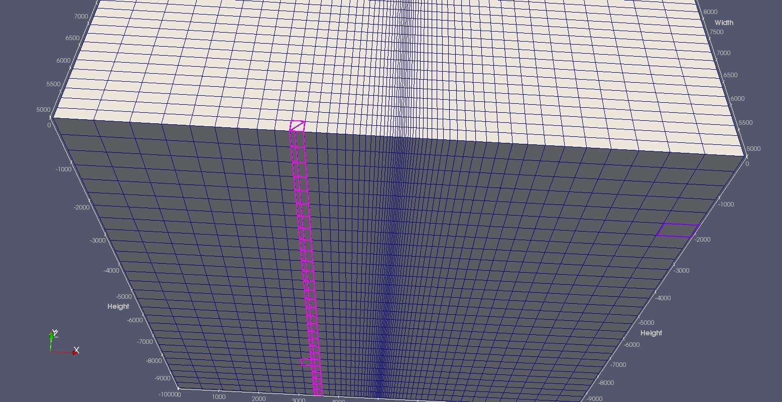
The selected vertical parts in pink are not the hexahedrons (cuboids). I do not know what happened during the transfer process.

I can not upload the .geo/.msh/.vtu files. So I list the content of .geo file.

Thanks for your help.

Yan

.geo file content:

a = 4964;
b = 72;
c = 10000;
d = 10000;
e = 200;
f = 26.666667;

//+
Point(1) = {0, 0, 0, e};
Point(2) = {a, 0, 0, f};
Point(3) = {a+b, 0, 0, f};
Point(4) = {2*a+b, 0, 0, e};
//+
Point(5) = {2*a+b, c, 0, e};
Point(6) = {a+b, c, 0, f};
Point(7) = {a, c, 0, f};
Point(8) = {0, c, 0, e};
//+
Line(1) = {1, 2};
Line(2) = {2, 3};
Line(3) = {3, 4};
Line(4) = {4, 5};
Line(5) = {5, 6};
Line(6) = {6, 7};
Line(7) = {7, 8};
Line(8) = {8, 1};
Line(9) = {2, 7};
Line(10) = {3, 6};
//+
Line Loop(1) = {1, 9, 7, 8};
Plane Surface(1) = {1};
//+
Line Loop(2) = {2, 10, 6, -9};
Plane Surface(2) = {2};
//+
Line Loop(3) = {3, 4, 5, -10};
Plane Surface(3) = {3};
//+
Transfinite Line{2, -6}= 4;
Transfinite Line{8, -9}= 51;
Transfinite Line{10, 4}= 51;
Transfinite Line{1, -7}=  28 Using Progression 0.8885;
Transfinite Line{-3, 5}=  28 Using Progression 0.8885;
Transfinite Surface{1,2,3};
Recombine Surface{1,2,3};
out[] =Extrude {0,0,-10000} { Surface{1,2,3}; Layers{28}; Recombine; };
Physical Volume("0") = {1,3};
Physical Volume("1") = {2};

Dear guoqiang-yan,

This is a display problem of Paraview. I have checked out the .vtu file generated from .msh file. It works fine.

Best regards,
Renchao Lu

Thanks Renchao.
Have a nice day.

Hello, Renchao,

Sorry to bother you again.

I rechecked my .vtu file on the Paraview. Anomalies are shown as follow:

  1. When I use the clip tool (using Y normal view), there are Wedge cells and Hexahedron cells in the cell list.

  2. When I use the ‘Select Cells On’ tool and ‘Extract Selection’ tool to select the anomalies cells, it is a Wedge cell with two separated faces on one face even though it is called Hexahedron.
  3. When I use the slice tool (using Y normal view), my file is different from your Benchmark file (ogs-data-master/Parabolic/HT/FaultedCube).

Thanks for your help.

Guoqiang

Dear Guoqiang,

Could you please upload your .vtu file?

Best regards,
Renchao

Hi Renchao,

I haven’t found a way to upload the mesh files on this website. Please download the mesh files on the following link.
https://www.dropbox.com/sh/rng5c42ugbxxdjc/AABNhnwwXh9nXcCUlzhtLdbya?dl=0

Thanks.

Guoqiang

Dear Guoqiang,

The .vtu file is all right. You may clip over the domain at different position. The Wedge elements will randomly show up. Nevertheless, this will not cause any problem on your modeling.

Best regards,
Renchao

Thanks for your help, Renchao.

I also checked OGS Benchmark mesh file (ogs-data-master/Parabolic/HT/FaultedCube). There were no anomalies I mentioned in this post appearing in the Paraview.

Furthermore, I simulated my problem using the mesh file. But I had not got my expected results. After checking all related factors, I doubted about the problem of mesh file again.

Could you share the .geo file of the OGS Benchmark file (ogs-data-master/Parabolic/HT/FaultedCube) or your related .geo file (using Extrude function in Gmsh) with me? Maybe there are problems in my .geo file.

Thanks again.

Guoqiang

There are no wedge-elements or tetrahedra in your file. I only found hexahedra in your file. As Renchao said, it’s a little visualization bug of Paraview.

Just try this: In Paraview, just visualize you cell data in a SpreadSheet View and arrange them along the cell type.

By the way, this is also a one way to eliminate unwanted element types, e.g. lines, etc.

Hello, Thomas,
Thanks for your suggestion.

Have a nice day.

Guoqiang