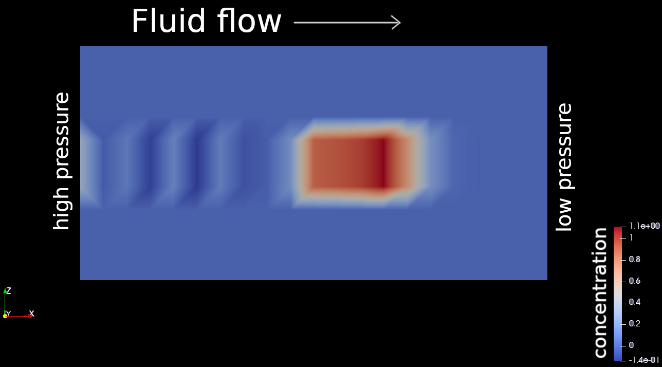
In a quite simple setup of a cuboidal initial concentration in a cuboidal domain, I obtain, in addition to the expected downstream transport, an implausible wave-like motion in opposite direction (there may be some plausible diffusion upstream, but much slower).
In the initial state there is just a red cube (concentration=1) in the center of the blue domain (concentration=0). After some time I obtain a distribution like in the attached picture, even with negative concentrations.
Did anyone encounter similar artefacts and knows which parameter(combinations) they depend on?
It was observed, that if there is a no-flux condition at the upstream boundary, then the errors pile up, whereas a Dirichlet condition (c=0) at this boundary limits the error.
Hi Domink,
Sorry for coming too late. If you set the diffusion coefficient to zero in the demonstrative testcase you are currently working on, it will be reduced into a classical pure advection problem where the sharp concentration discontinuity can no longer be preserved due to numerical oscillation. This is because we employ the standard finite element method for the ComponentTransport module. As you observed, numerical artefacts appear severe in the advection-dominated mass transport problems. Such numerical instability issue has been systematically investigated. To my knowledge, you might adopt one of the following stabilization schemes to mitigate the numerical artefacts: 1) SUPG method; 2) Galerkin/least-square (GLS) approach; 3) FCT algorithm; and etc. I hope my answer swipes your doubt.
Best regards,
Renchao
Thank you for the explaination, so I know how to classify the oscillatory
artefacts.
Just to be sure, these schemes (SUPG, GLS, FCT) are not yet available in OGS and need to be implemented?
Yep, these stabilization schemes are yet not available in the ogs release.