, producing a mesh with GMSH and converting it to OGS with the tool GMSH2OGS.
I am wondering what is the best strategy to define the internal holes boundary condition.
I am using the utility ExtractBoundary and then, manually, I filter out in Paraview each one of the circle … however it is quite time consuming.
Is there a way to define the different boundaries Id in GMSH, so then the routine ExtractBoundary provides each boundary separated? any ideas?
To my knowledge, there is no OGS tool currently, which could extract boundaries automatically.
I could imagine, that gmsh to vtk converter could be extended to generate the boundary meshes as there is some information from gmsh on physical entities/material ids.
Thanks for your answer, defining the future polylines in GMSH as Physical Curves makes easier to prepare the geometry .gml file.
I prepared a Python script to prepare the gml file from GMSH mesh, I will share it here in the next days.
I know that extracting nodes/polylines/surfaces directly from Paraview is more robust, but sometimes it is easier to have a fixed geometry .gml and changing the mesh (for example for mesh convergence tests), trusting the node search capabilities of OGS.
Here attached the python script and an application example (both poorly written, quick&dirty, .gmsh-gml_ogs6.zip.zip the python script comes with no guarantee whatsoever)
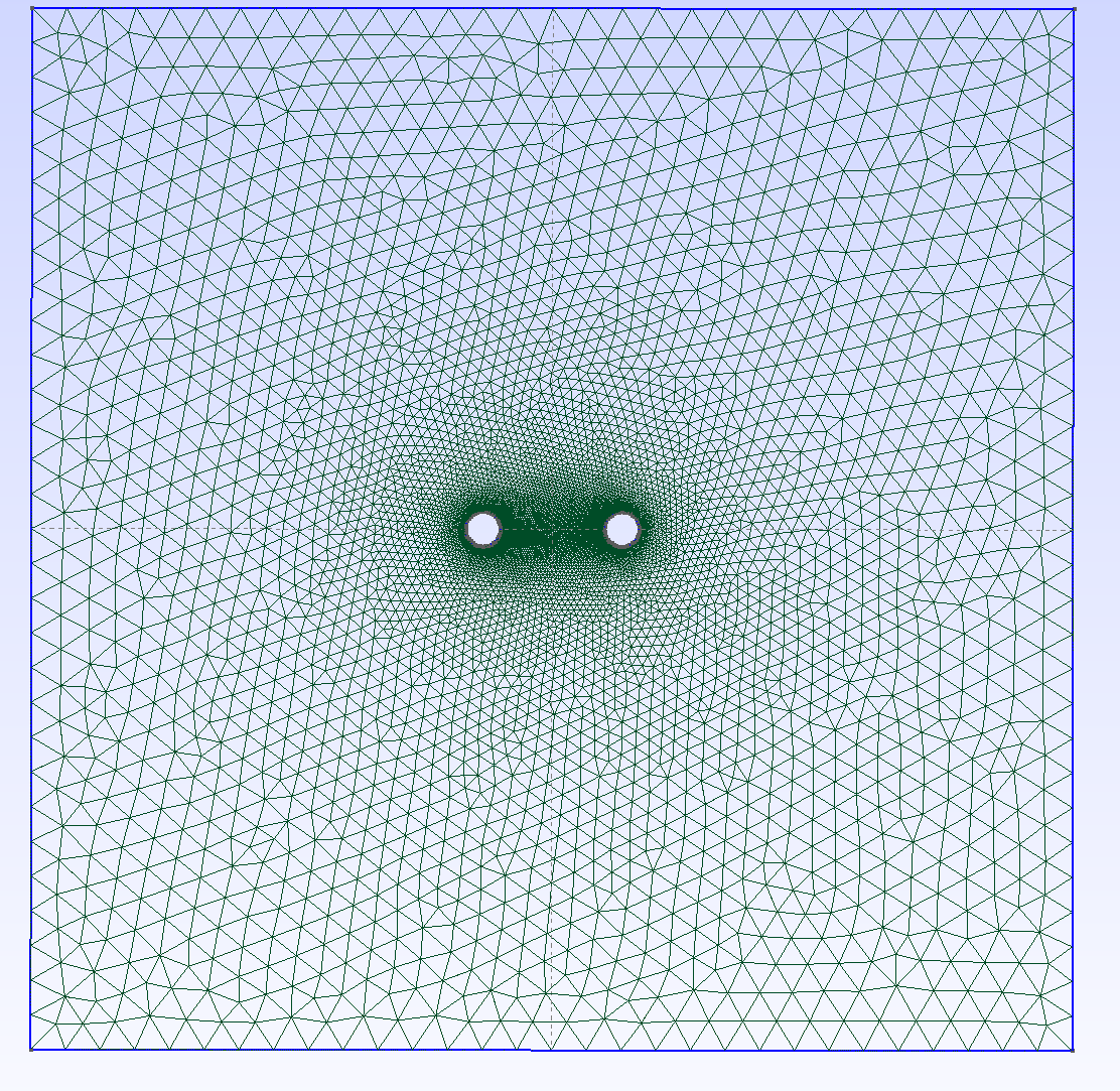
The file gmsh_coarse.geo provides the input for GMSH, to build a rectangle with two holes, with the following physical groups defined:
3 physical surfaces: the rectangle minus the 2 holes, the hole on the left and the hoel on the right
5 physical curves: the 4 borders of the rectangle plus 2 curves defining the circle boundary of each holes.
The mesh generated with GMSH must be saved as GMSH v.2, as always (for example as gmsh.msh, like here )
The script msh2gml.py will then prepare the geometry mesh.gml starting from the gmsh.msh file (Have a look at the Note at the bottom of this message).
Then the mesh is prepared with various iterations of manual editing of the gmsh.msh to remove the holes material, NodeReordering , Paraview to add PointData and CellData, etcetc…
Note: the gml file generated this way almost always produces a segmentation fault error in OGS6 (serial, Singularity container).
For some reasons I don’t understand, manually adding a point (for example, a point id=“236” x=…) before the first point id output by the script makes OGS6 happy.
An example of this behavior can be seen in the simle example attached ( seg_fault.zip (25.7 KB) ) simply by using either geometry_1.gml (ogs6 crashing) or geometry_2.gml (random point added, not used in any polylines, but ogs6 is happy).
I think OGS6 expects that the point IDs in the gml file are zero-based numbered. In the file geometry_1.gml I decreased the point ids and changed also the IDs referencing the points in the polyline. Then the file is loaded without an error message.
Related question (I cannot test it, I have no access to my machine now): do the point IDs need to be in order?
From what I understand, even if I had my points ID defined, then in the polylines it is not the IDs that are read, but only the position of the nodes. In my example the SegFault was coming only because the polyline was asking for the node 114, which was missing in the nodes list because I had only 113 nodes, numbered 1-114 … since no polylines was calling the node 0, I was then ok with having an arbitrary node at the beginning.
Anyhow, It would be good to have the .gml specifications written here (indexing, ID must be number/string and when it is used etcetc):
Yes, it is a good idea to put it there.
Especially because our GML file format has nothing to do with the Geography Markup Language, which might be also confusing for some people and there is no external software that is able to write GML files. The specifications of the GML file are somehow given in doxygen.
E.g, OGS: [attr] id
There, it is written that the ID is of type size std::size_t. However, I think, we cannot expect from every user to know what it means.
I am afraid, my question is about meshing, but not related to the previous discussion.
Does anybody have a minimal example (input files, ideally *.grd surfer files for the rasters) for createLayeredMeshFromRasters?
I tried a minimal example (createLayeredMeshFromRasters -i mesh2d.vtu -r surfing_carpets -o mesh3d.vtu) producing a segmentation fault.
Unfortunately, as a new user I can not upload the corresponding input files.
I haven’t worked with raster files yet. However, what quite often leads to segmentation faults during I/O are degenerated elements.
How did you create mesh2d.vtu? Creating 2D-meshes with paraview from 3D objects/elements often leaves degenerated 3D elements in the vtu file. These can be filtered with the mesh quality filter and the spreadsheet view.
Thank you Lurpi, I already scheduled gmsh, particurlary its python-API, for the mesh generation.
I was only wondering, if this was already done, i.e. save this efforts.
Anyway, gmsh gives tight control over the meshing.
I did not suceed to import/convert gmsh-meshes by the ogs-utils, so I tried meshio to extract domain and boundary meshes, still there is some trouble. The current state is https://github.com/dominik-kern/msh2vtu
For domain meshes, subdomains can be adressed by “MaterialIDs”, is there a way to do the same for boundary meshes? So we would need only one boundary mesh and specify its subdomains by “physical IDs” (in terms of gmsh) instead of many boundary meshes, one for each BC.
For the conversion from gmsh- to vtu-files I wrote a script that also extracts boundary- and subdomain-meshes (defined as physical groups in gmsh): msh2vtu
Currently restricted to 2D-triangle-meshes.
I would be happy about any feedback.
I am happy to annouce that 3D functionality is enabled.
Still msh2vtu is limited to linear simplex elements.
So after conversion of linear meshes from Gmsh to vtu-format, createQuadraticMesh and identifySubdomains may lead to quadratic meshes (e.g. for HM models).
I will next look what possibilities there are to directly create higher order meshes from Gmsh or via meshio.
The current version was tested on two examples, one 2D and one 3D, any further feedback is appreciated.