Dear Yasin,
I have found the reason of your problem. First let me show what I did.
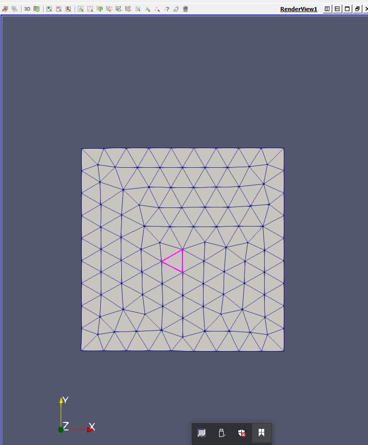
You can load the mesh file (regular_beier.vtu) into Paraview and render it in 3D with the option “Surface with Edges”. Here I just used the “select on” tool to select one prism element, as shown in purple color in the following figure.
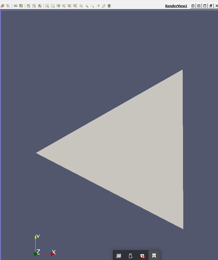
Then I added a filter called “extract selection”, which will extract exactly this element. That’s how it looks like.
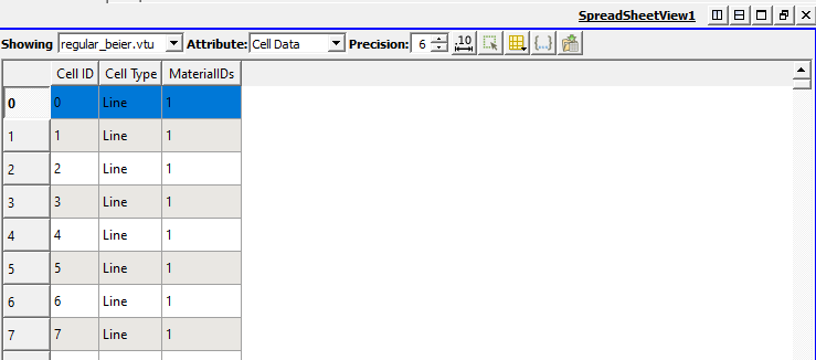
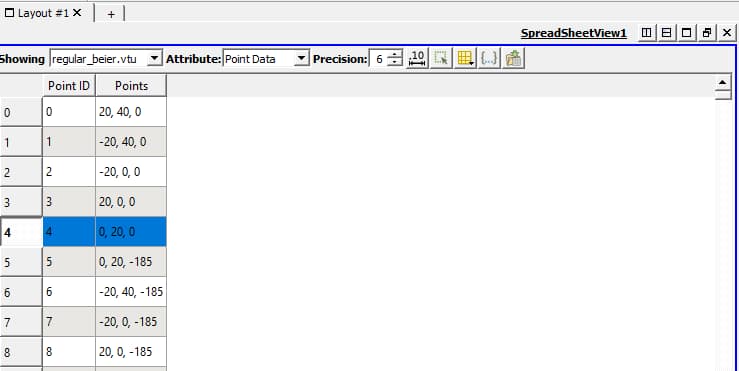
By adding a second view window, and convert the the extracted selection to the spreadsheet view, you can see the exact info of this selected element, by choosing Attribute to “Cell Data” (not shown here). So it tells me the selected element has an index of #15799.Then I would like to know which nodes are connected by this element, so I changed the Attribute to “Point Data”, the spreadsheet view shows the following.

From above, there are 6 nodes to form this element, i.e. #10266, #9731, #11513, #632, #627, and finally #4. Among them, #11513 and #4 are the nodes sitting on the location of the BHE. To make the simulation right, these two nodes have to be the first two nodes forming the BHE line elements. This has to be confirmed. I then switched the Showing data to “regular_beier.vtu” in the spreadsheet view.
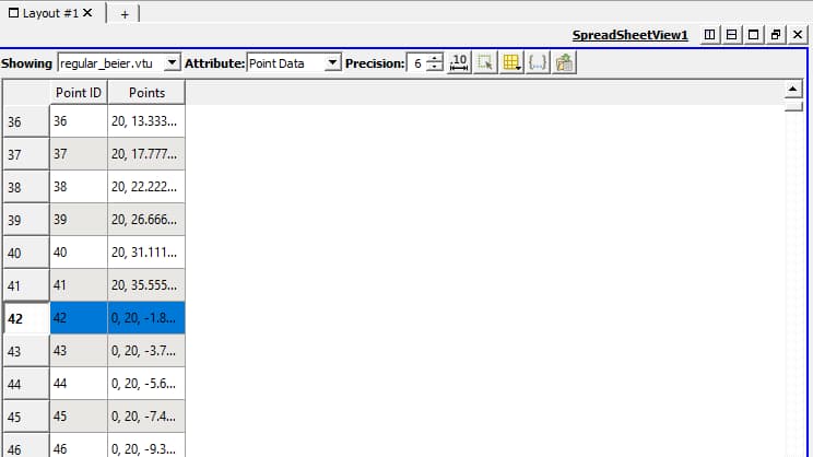
After selecting the first line element, it turned blue. Now by changing the Attribute to “Point Data”, Paraview will tell you which nodes are connected with this line element.
It is clear that the first BHE line element is actually formed by node #4 and #42, not #4 and #11513 as it should be. By looking at the z-coordinates, it also tells that #42 and #11513 are two different nodes at different locations.
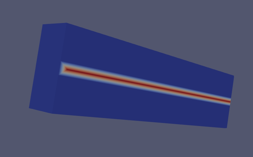
Up to this point, the reason of your non-physical simulation result is clear. The BHE elements are not correctly formed. In order to make the heat exchange between BHE and soil to work correctly, one needs to form the BHE elements using existing nodes from the soil part. In this case, this means the BHE elements should be #4 and #11513… In another word, we are re-using the same nodes in the the soil domain to form a second domain representing the BHE. Without this structure, the HEAT_TRANSPORT_BHE feature does not work. You may want to repeat the same procedure on mesh files of the existing benchmarks to see the difference.
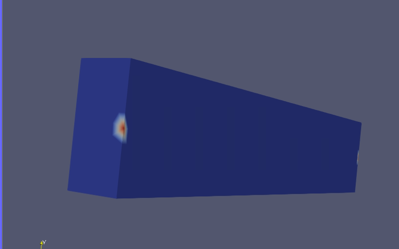
Physically speaking, what you set up in your model is a BHE that is just touching the soil at both ends (at 0 and -185 m). In the middle, you have some random nodes, which have not heat exchange with soil. Although you can have the model run and converge, there is no actual heat exchange between the BHE and soil, except at the two ends. That is what you asked the OGS to simulate, and that is exactly what you got in the result, i.e. elevated temperature at two ends.
So to fix this, you need to change the mesh configuration. We typically use a script to pick up the nodes lying on the BHE location and adding the line elements to the existing mesh. Please contacting Jacob Randow ([email protected]), he can provide you the script and explain you how to do this. Please also let us know once you figured it out.
Have fun with OGS and best regards,
Haibing